Ditching the Pi: Building a Wireless, Solar-Powered ESP32 Soil Sensor
Sometimes, you just need a break from differential equations and advanced engineering mechanics problem sets to build something tangible. I recently set out to create a wireless, outdoor soil moisture sensor, but my initial thought—using a Raspberry Pi—was massive overkill. The Pi is a power-hungry Linux computer, and keeping it alive in the dirt would have been a nightmare.
I needed an “avionics” approach for the backyard: lightweight, purpose-built, and highly efficient. That meant pivoting to the ESP32 microcontroller and rethinking my power supply entirely. Here is how I designed a “Swap & Go” AA-powered soil sensor that can survive the elements and run for months on a single charge.
Why the ESP32 and Why a Solar Li-Po?
The magic of the ESP32 is its “Deep Sleep” function. It can power down its Wi-Fi radio and drop its current draw to practically nothing (~10µA), wake up on a timer, take a reading, transmit the data, and immediately go back to sleep.
Initially, I looked into a 4x AA battery pack from Adafruit. By loading it up with four NiMH rechargeable batteries, I got a nominal output of 4.8V, which is the absolute sweet spot for the ESP32. When the system eventually pinged me with a low-battery alert, I would just walk outside and swap the AAs.
The only issue with this design was it wasn’t truly autonomous. I would still have to go out and change the batteries every now and then. I did a bit of digging and found out about weather-resilient Li-Po batteries from this paper. From this, I went back to my original idea of a rechargeable Li-Po battery.
To make the system a true “set and forget” device, I paired the battery with a small 5V mini solar panel. The solar panel routes power directly into a TP4056 charging module. The TP4056 is the unsung hero of this build: it takes the fluctuating voltage from the sun, safely regulates it to charge the Li-Po cell, and provides built-in protection circuits. During the day, the sun trickles enough power into the battery to easily cover the tiny energy debt incurred by the ESP32’s brief wake-up cycles.
Now, just like on your phone, over time the life of the battery degrades if you cycle it too much. To prevent this, I would only charge the battery to around 80% and start the recharge process when the battery dropped below 20%. I was able to come to this conclusion based on these calculations:

The Bill of Materials
If you want to replicate this, here is exactly what you need:
ESP32 Development Board: Look for an ESP32-WROOM-32 Dev Kit with pre-soldered headers.
Capacitive Soil Moisture Sensor (v1.2 or v2.0): This is critical. Do not buy the cheap “resistive” sensors with bare metal prongs. They suffer from electrolysis and will corrode away into the soil within weeks. Capacitive sensors are encased and measure moisture via changes in capacitance.
5V Mini Solar Panel: A small 1W to 1.5W epoxy solar panel is perfect.
TP4056 Battery Charger: A popular, low-cost, and complete linear charger integrated circuit with battery protection.
1x Weather Hardened Li-Po or 18650 Battery: Ensure it has enough capacity (e.g., 2000mAh+) to survive cloudy weeks.
Battery Holder: A standard 18650 or Li-Po enclosure to keep the cell secure.
Waterproof Junction Box: An IP65 or IP67 rated plastic enclosure (roughly 100mm x 68mm x 50mm).
Cable Gland (PG7): To create a waterproof seal where the sensor wires exit the box.
Misc: Female-to-Male jumper wires, a few packets of silica gel (desiccant), and optionally some clear nail polish or conformal coating.
The Wiring Strategy (The Battery Saver Hack)
Wiring this up is straightforward, but there is one major hardware trick you need to implement to save battery life.
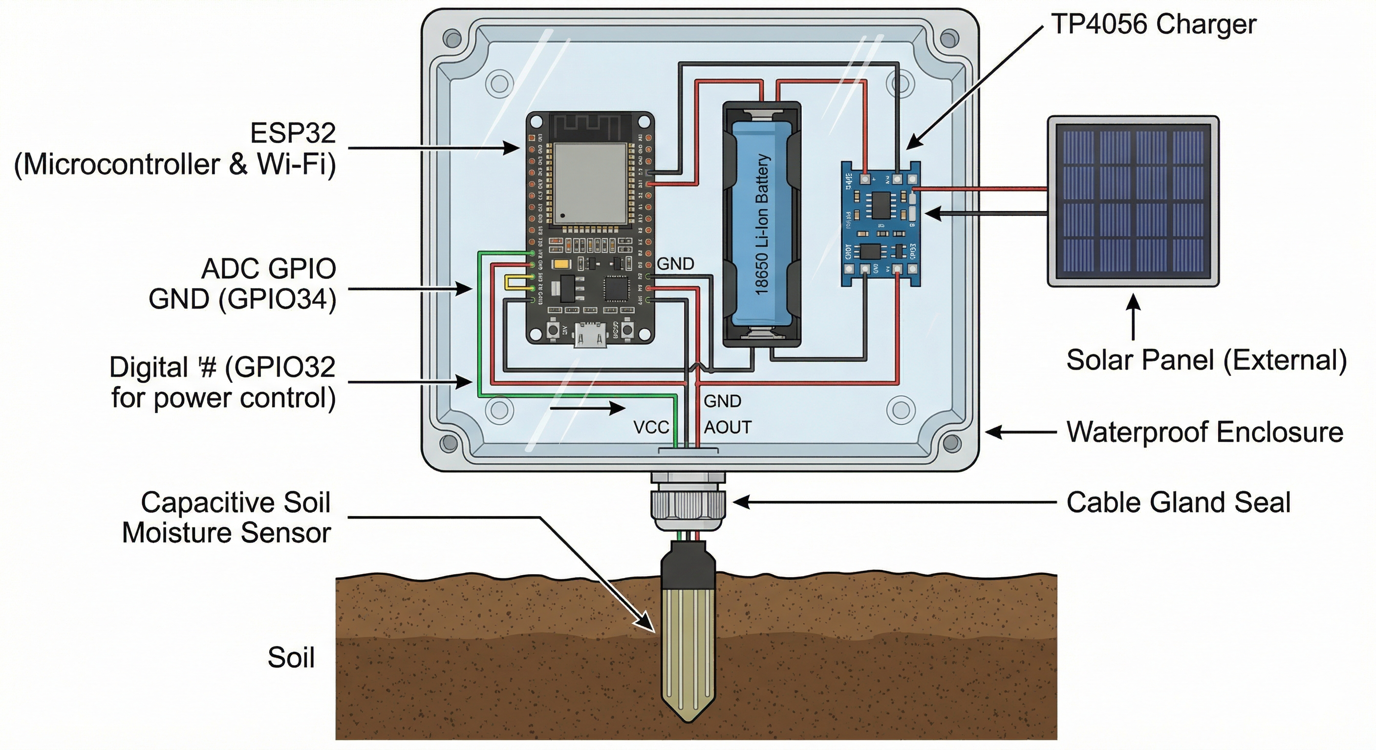
- Solar & Charging: Connect the positive and negative wires from the solar panel to the
IN+andIN-pads on the TP4056. Wire your battery to theB+andB-pads. - Main Power: Connect the
OUT+from the TP4056 to the VIN (or 5V) pin on the ESP32. ConnectOUT-to a GND pin. Never connect the battery directly to the 3V3 pin, or you’ll bypass the regulator and fry the board. - Sensor Data: Connect the analog output (AOUT) of the sensor to GPIO 34.
- Sensor Power (The Hack): Do not connect the sensor’s VCC to a constant 3.3V pin. If you do, the sensor will draw power 24/7, killing your Li-Po battery over a few cloudy days. Instead, connect the sensor’s VCC to a digital pin (like GPIO 17). In your code, you can set this pin
HIGHright before you take a reading, and set itLOWimmediately after.
Weatherproofing for the Real World
Building the circuit is only half the battle; the other half is making sure the morning dew doesn’t short the whole thing out.
The ESP32, TP4056, and battery sit snugly inside the waterproof junction box. To get the sensor outside, I drilled a hole in the bottom of the box, installed the PG7 cable gland, and passed the sensor wires through, tightening the nut to compress the rubber seal around the cables. The solar panel gets mounted to the lid, with its wires fed through a second, smaller sealed hole.
Because temperature swings can cause condensation inside a sealed box, I tossed two small silica gel packets inside before screwing the lid shut. For extra peace of mind, you can brush a layer of clear nail polish over the exposed components on the ESP32 board (avoiding the USB port and the metal Wi-Fi shield) to act as a poor man’s conformal coating.
The hardware is solid, the power math checks out, and it’s ready for the dirt. Next up: writing the C++ code to handle the Deep Sleep cycles and Wi-Fi transmission.